Hardware Demo of a Digital PID Controller
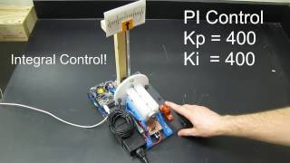
The demonstration in this video will show you the effect of proportional, derivative, and integral control on a real system. It's a DC motor connected to an optical rotary encoder (quadrature) and is controlled by a digital control loop implemented on a TI Launch Pad MSP432. It uses a series of timers and interrupts to generate the PWM signals to the H-Bridge motor driver, read the pulses from the encoder, and calculate the control effort using a PID control algorithm. It also implements an anti-windup algorithm to improve the system stability since this is a real system and the motor saturates easily.
If you listen, you can hear the PWM signal whine as it adjust the current to the motor. When I push on the flag with my hand you will hear it go quiet. That's when the PWM is at 100% duty cycle and the audible PWM AC current going to the motor is now DC.
Post a comment if you liked the video!
You can download the code, design files, and parts list here:
https://github.com/arduinoNube/digital-pid-classroom-demo
(out of date: https://sourceforge.net/projects/digital-pid-controller-msp432/ )
Enjoy!
http://www.gregoryholst.com
 10:36
10:36
 22:19
22:19
 28:57
28:57
 10:33
10:33
 15:29
15:29
 2:15:52
 13:20
13:20
 13:07
13:07
 8:55
8:55
 13:13
13:13
 49:18
49:18
 16:12
16:12
 8:43
8:43
 7:08
7:08
 9:30
9:30
 26:29
26:29
 25:56
25:56
 14:34
14:34
 20:06
20:06
 27:11
27:11