How to Size a Control Valve for Liquid Flow
Learn more about sizing control valves for liquid flow and the steps that go into the process for proper sizing. This video is a step-step procedure for the sizing of control valves for liquid flow using the ISA and IEC procedure. Each of these steps is important and
must be considered during any valve sizing procedure.
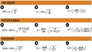
1. Specify the variables required to size the valve as follows:
Desired design
Process fluid (water, oil, etc.), and
Appropriate service conditions
q or w, P1, P2 or ΔP, T1, ρ1/ρo, Pv, Pc, and ν
2. Determine the equation constants, N1 and N2.
3. Determine FP, the piping geometry factor, and FLP, the liquid pressure recovery factor adjusted for attached fittings.
4. Determine the pressure drop to use for sizing, ΔPsizing.
5. Calculate Cv. If this Cv value is not close to the estimate used in step 3, iterate using
this new Cv value and the corresponding FL from the product information.
Additional Resources:
– Control Valve Handbook https://www.emerson.com/documents/automation/control-valve-handbook-en-3661206.pdf
Thanks for watching! Please like, share, and comment on our video and make sure to subscribe to the Fisher Valve & Instruments channel.

 3:18
3:18
 5:21
5:21
 11:04
11:04
 9:44
9:44
 12:42
12:42
![Wizyta Na Komisariacie (NOWOŚĆ 2025) - Kabaret Moralnego Niepokoju, Młodzi i Moralni [E10E7]](https://i.ytimg.com/vi/GKfbH4va7gk/mqdefault.jpg) 2:14:24
2:14:24
 6:31
6:31
 1:00:19
 4:05
4:05
 20:39
20:39
 32:50
32:50
 9:33
9:33
 4:39
4:39
 13:53
13:53
 10:38
10:38
 6:26
6:26
 4:43
4:43
 8:54
8:54
 6:54
6:54
 18:28
18:28