4½ Practical Uses for a Diode
... and a diode basics crash course
1-Click Subscribe! ► http://bit.ly/KLabs_sub ◄
Testing Components with an Oscilloscope: http://bit.ly/Comp_Testing
Questions? Ask me on Twitter:
https://twitter.com/DanielBogdanoff
Check out the Keysight Podcasts YouTube channel:
http://bit.ly/KeysPodcastSub
Facebook:
https://www.facebook.com/keysightbench/
Transcript:
Today we’re going to look at 4 ½ diode tricks that you can use in your designs.
The diode is a fundamental component you have to understand if you want to grow your electronics prowess.
Diodes are generally the first non-linear component one learns about.
Resistors, capacitors, and inductors are all linear devices, meaning that if you were to plot the input voltage vs. the output voltage, you’d get a plot straight up and to the right.
Nonlinear devices don’t follow Ohm’s law, and for circuit analysis you cannot replace them with a Thevenin equivalent.
Diodes are also passive devices, which means they don’t need power to function. Finally, they are two port devices, meaning there’s just one input, the anode, and one output, the cathode.
When operating normally, an ideal diode only conducts current in one direction.
They’re conceptually quite simple, but are extremely useful because of their V-I curve. The x-axis is voltage, and the Y-axis tells us how much current can flow through the device when exposed to that level of voltage.
At moderate positive voltages, a diode essentially acts as a short, but with a small voltage drop called the “forward voltage drop.” You can see the forward voltage drop on the VI curve - around .6-.7 V, where the current starts to ramp up. That .6/.7V drop is standard for silicon diodes, but for other types of diodes and materials this forward voltage drop may vary.
You can measure this forward voltage drop for a specific diode using a multimeter with a diode testing capability.
You can see that this diode has a forward voltage of roughly .62V.
The forward voltage is also sometimes called the “cut-in voltage” or the “on voltage.”
But what you need to remember is that, when exposed to a moderate voltage – say 5V – A diode will pass through 5V minus the forward voltage. So, 4.3V for a standard silicon diode.
When exposed to a negative voltage, there will be a nano-amp reverse current (or current from the cathode to the anode) that you can generally take to be 0A in most situations. That is, until you get to the other big swing on the VI curve – known as the breakdown voltage. If your diode is exposed to this level of reverse bias, you blew it. Diodes essentially can’t hold up to that level of negative voltage stress and the device literally breaks down - allowing negative current flow.
Tip #1: rectifiers
The gist is that you can let through the positive voltages from an AC source while blocking or inverting the negative voltages.
You can put together a halfwave rectifier with a single diode or a full bridge rectifier with four diodes.
It’s worth noting that you have to use a differential probe to measure a full bridge rectifier with an oscilloscope.
Bring a capacitor into the mix, and you can:
1. smooth out a rectifier (although it’s generally better to use an active voltage rectifier chip)
2. build a voltage multiplier, which is essentially a bunch of half wave rectifiers in series. This is used for things that need high voltage but not a lot of current, like electric bug zappers and particle accelerators.
Tip #2 – diode logic gates
You can build simple logic gates using diodes.
You can create an n-input OR gate or AND gate using 1 diode per input.
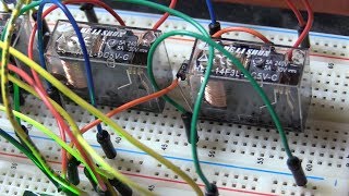
For more practical scenarios, you can do some less-standard “logic.” Take, for example, a battery backup system. Using two diodes, you can pass either the intended voltage input (if present), or the battery source.
Tip #3 – diode clamps
You can use diodes to limit the range of a signal. You can essentially pre-clip the signal by connecting a diode to a reference voltage or a voltage divider.
If we start with a standard triangle wave, the signal looks normal on the scope. But, when we add the diode + resistor clamp attached to a positive reference voltage, the signal starts to clamp. If I adjust the reference voltage, we can see the clamping levels change.
Clamps can also provide DC restoration when used with a capacitor. For example, if a signal has been capacitive coupled, you could setup a diode and capacitor like this to restore it’s positive DC component.
Tip #4 – Flyback Diodes
Flyback diodes are the pressure release valves of the electronics world. Because inductors resist a change in current you can’t just instantaneously turn them off – they’ll fight back against the control circuitry to the point that it can shorten its life or blow it up.
#Diode #electronics #diodecircuit #circuit #rectifier #flyback #oscilloscope #Keysight #multimeter #DiodeTester #Whatisadiode #howtouseadiode

 19:50
19:50
 18:53
18:53
 18:18
18:18
 3:23:00
 31:14
31:14
 32:34
32:34
 1:15:11
 9:21
9:21
 18:07
18:07
 17:38
17:38
 18:56
18:56
 33:28
33:28
 39:28
39:28
 12:17
12:17
 10:21
10:21
 27:05
27:05
 4:20
4:20
 22:18
22:18
 35:54
35:54
 7:40
7:40