**More details here, please read**
This video shows how to measure FM Frequency Deviation using the Carrier or Bessel Null method. Ideally, no special equipment is needed besides a CW receiver capable of tuning to the FM transmit frequency, an audio generator, a method of properly adjusting the the audio into the transmitter, and a safe way of coupling the TX output into the receiver. This method takes advantage of the fact that the carrier of an FM signal modulated with a single audio tone will pass through zero (a null) at specific combinations of modulating frequency and deviation.
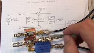
The setup I show is a little more complex because I don't have a CW receiver that operates on 2 meters, so I had to use a mixer to downconvert the 2m signal to an HF frequency. In this case, I used 10.7MHz because I had a ceramic resonator that could be used as an IF filter following the mixer. I also used a splitter in my setup so that I could also send the transmitted signal to a FM deviation meter to double check the deviation measurement.
Here is a link to the video on the mixer I used for the downconversion:
http://www.youtube.com/watch?v=Mm7WfVzr1ao
Here is the link to the video on RF Samplers, like the one I used to couple the transmitter output into the mixer and deviation meter:
http://www.youtube.com/watch?v=0Kk_N_TpDeo
You will want to carefully adjust the CW receiver's passband to ensure that only the carrier is being measured, and not any of the sidebands. This is usually not a problem. Alternatively, you can use any one of a number of free programs that show you the audio spectrum, waterfall plots, etc., such as those used for PSK31, etc., or even free audio spectrum analysis software such as Spectrum Lab, to monitor the level of the carrier tone - even in the presence of the sideband tones. If your rig has a spectrum monitor function, you may even be able to use that. Just pick the method that works best for your CW receiver to monitor the level of the carrier tone as you vary the audio tone.
If your audio generator doesn't have an accurate frequency readout, remember that most decent DMMs can measure the frequency of audio tones, so use that.
You do have to take care in setting the audio level from the audio generator into the mic input of the rig. Note that some rigs have a DC bias on the audio line, so it's a good idea to couple the signal through a large value capacitor - preferably a non-polarized electrolytic. Typical mic levels are 10s of millivolts, so if your audio generator output can't be dialed down that low, you'll have to attenuate it with a voltage divider, pot, or attenuator. I used a variable attenuator in my setup. The rigs will generally have some audio compression circuitry, so if input signal is driven too hard, it will internally limit it to prevent over-deviation or audio clipping. Of course, these circuits aren't perfect, so be cautious. It is helpful to monitor/listen to the rig's output on an FM receiver as you adjust the audio level. Increase the level until the perceived volume is no longer increases. This means you've generally hit the max deviation of the transmitter.
Please let me know if I left out any critical details that you might need. And of course, take great care in your setup anytime you are connecting a transmitter directly to a receiver!!! This is why I have the transmit power turned all the way down, and I am using a RF tap that has at least 40-50dB of attenuation, and I have the attenuator enabled on the receiver. If you are unsure about it, then simply transmit into a dummy load and use an antenna on the receiver - there should be enough leakage for you to pick up the signal.

 17:27
17:27
 44:10
44:10
 11:16
11:16
 12:20
12:20
 6:01
6:01
 9:08
9:08
 30:15
30:15
 19:50
19:50
 25:06
25:06
 22:17
22:17
 5:11
5:11
 16:21
16:21
 29:36
29:36
 27:58
27:58
 8:24
8:24
 34:24
34:24
 28:02
28:02
 14:32
14:32
 19:02
19:02
 11:44
11:44